Ray Optics Module
Table of contents
 Activity 1

-
Imagine a room that contains a light source, L, a plant P, and an observer with an eye, E, as shown. Sketch the situation in your notebook and some rays that will allow the observer to see the plant. If light is reflected, indicate if the reflection is diffuse or specular.

-
Imagine a room that contains a light source, L, a plant P, an observer with an eye, E, and a mirror, M, as shown. Sketch the situation in your notebook and some rays that will allow the observer to see the plant in the mirror. If light is reflected, indicate if the reflection is diffuse or specular.
Activity 2
Here is a picture of Jason Harlow in front of a chalk-board, reversed several times to produce 4 possibilities. One image is the original, one is reversed left and right, one is reversed up and down, and the other is reversed both left and right and up and down.
|
1 |
2 |
|
3 |
4 |


-
Can you tell which image of Harlow is the original (1, 2, 3 or 4)? Explain your reasoning. [Note: this question is meant for fun and may end up being more about fashion trends than physics – but it is meant to get you thinking about image reversal.]
-
“Why do mirrors reverse left and right and not up and down?” Alice and Bob stand in front of a large mirror in a dance studio, looking at themselves. Alice wonders if their images are reversed “left and right” or “up and down”. She looks at Bob’s image in the mirror and memorizes what he looks like. Then she asks Bob to turn and face her, so she can compare the image to what Bob looks like in real life. Bob takes a couple of steps forward, turns around and faces Alice. Alice notes that, compared his the mirror image, Bob appears reversed left and right! Alice concludes: Mirrors reverse left and right, not up and down. Is this true? Can you see any flaws in Alice’s reasoning?
-
You are supplied with a small sign on which is printed “Charles Dodgson”, which was Lewis Carroll’s real name. Hold the sign up to the supplied mirror with the writing facing the mirror: you will see the text in a mirror image. Now hold the sign up to a light and look at the writing on it from behind. Is there any difference between the appearance of the writing as seen in the mirror and the writing as seen from behind? Now curve the sign so the edges are closest to you and centre, about where the D is, is furthest away from you. Look at the sign in the mirror. In the mirror image are the edges curving towards you or away from you? In Part B, you may have concluded that mirrors reverse left and right. Do you want to change that conclusion? What do mirrors really reverse?
 Activity 3
This activity uses the “Ray Box” feature of the PASCO Basic Optics Light Source. Place the light source flat on the table or on your notebook so it is sitting on its four little legs and plug it in. There is a wheel to select one, three or five parallel rays projected onto the table. If you place it on your open notebook the rays will be easier to see and you can trace them with a pen or pencil.
You also should have a transparent glass trapezoidal prism, a small protractor and a ruler.
Trapezoidal prism: 
-
Select the 1-ray and shine it on an open page of your notebook. Place the trapezoidal prism in the beam. You should see that part of the ray is refracted through the trapezoidal prism, but there also is a reflected ray. Adjust the angle of incidence. How does the brightness of the reflected ray vary with the angle of incidence? [Note, the angle of incidence is defined as the angle between the incident ray and the normal from the surface which emerges at the point where the ray touches the surface.]
-
Choose an angle of incidence, and carefully sketch and label the incident ray, the reflecting surface of the trapezoidal prism, and the reflected ray. Use the ruler and protractor to sketch and label the normal to the surface at the point where the ray reflects. Measure the angle of incidence and angle of reflection. Is the Law of Reflection obeyed to within your errors? Repeat twice for a total of three different incident angles. What is the largest source of error in measuring these angles?
-
Select the 1-ray and shine it on an open page of your notebook. Place the trapezoidal prism in the path of the ray so that:
-
the angle of incidence is at least 45°, and
-
the ray emerges from the other side of the trapezoidal prism. The side from which the ray emerges should be parallel to the side into which the beam enters. You should note that the emerging ray is parallel to the incident ray.
-
Sketch and label the incident ray and the surface of the trapezoidal prism through which you are refracting, the emerging ray, and the surface of the trapezoidal prism from which the ray emerges. Remove the trapezoidal prism, use the ruler to clearly mark all three parts of the ray, including the ray when it is inside the trapezoidal prism. Note that if you sketched the sides of the trapezoidal prism by running a pen along the surface, the line you drew will be about 1 mm in front of the actual glass surface; you should correct for this. Use the ruler and protractor to sketch and label the normals to the surface where the ray enters and exits the trapezoidal prism. Measure the angle of incidence and the angle of refraction for the ray when it first enters the trapezoidal prism. Use Snell’s Law to determine the index of refraction of the glass.
Activity 4
Here is the URL of a Flash animation of a ray of light traveling between air and glass.
Open the animation. There are two scenes you can toggle through: the first is of a ray traveling from air into glass, and the second is of a ray traveling from within some glass out into air. You may set the index of refraction of the glass within the range n = 1.25 to n = 1.75.
-
In the Air to Glass scene, set nglass = 1.5, and explore various angles of incidence. Record what happens for angles of incidence θ = 0°, 5°, 40°, 50°, 85° and 90°. Note the strengths of the reflected and refracted rays, if they exist, and the angle of refraction.
-
In the Air to Glass scene, set the angle of incidence to θ = 45°, and explore various indices of refraction of the glass. Record what happens at the minimum nglass, and what happens as you increase nglass.
-
In the Glass to Air scene, set nglass = 1.5, and explore various angles of incidence. Record what happens for angles of incidence θ = 0°, 5°, 40°, 50°, 85° and 90°. Note the strengths of the reflected and refracted rays, if they exist, and the angle of refraction.
-
In the Glass to Air scene, set the angle of incidence to θ = 45°, and explore various indices of refraction of the glass. Record what happens at the minimum nglass, and what happens as you increase nglass.
Activity 5
This Activity uses canola oil from the grocery store. Please avoid getting the oil on the tabletop or the floor. Please avoid mixing the oil with the supplied water.
- Pyrex glass has an index of refraction of 1.47, water has an index of refraction of 1.33, and canola oil has an index of refraction of about 1.47 depending on the brand. All three materials are transparent. You have a bottle of water with a test tube of water, and a test tube of oil in it. You also have a bottle of oil with a test tube of water, and a test tube of oil in it. Before analysing the test tubes in the bottles, predict what you will see when you dip the test tubes in and out of their respective bottles.
- Test your predictions from Part A. Keep the bottles over the supplied tray at all times to avoid making a mess on the tabletop. Describe and explain your observations. Please avoid getting canola oil in the water. Depending on the brand of canola oil, what you see when you first dip the canola oil test tube into the canola oil bottle may be a surprise.
When you are finished with this Activity, please dispose of any used Kleenex or paper towels, being careful not to get any oil on the tabletop or floor.
Activity 6
This activity uses the “Ray Box” feature of the PASCO Basic Optics Light Source. Place the light source flat on the table or on your notebook so it is sitting on its four little legs and plug it in. There is a wheel to select one, three or five parallel rays projected onto the table. If you place it on your open notebook the rays will be easier to see and you can trace them with a pen or pencil.
You also should have a flat glass convex lens, a flat glass concave lens, and a ruler.
|
Convex Lens: |
|
Concave Lens: |
|


-
Select the 5-rays and shine them on an open page of your notebook. Take the convex lens and focus the rays, so that the focal point is on your page. Sketch the five rays and the exterior shape and position of the lens. Label the focal point. Measure the focal length of the lens, which is the distance between the centre of the lens and the focal point (the point where all of the initially parallel rays converge to).
-
Select the 5-rays and shine them on an open page of your notebook. Take the concave lens and de-focus the rays. Leave enough room on the page so that you will be able to sketch the rays backwards to the virtual focal point from which they appear to be emerging. Sketch the five rays and the exterior shape and position of the lens. Remove the lens and use a ruler to trace the rays backward to the spot from where they all seem to be emerging. Label the virtual focal point. Measure the focal length of the lens, which is related to the distance between the centre of the lens and the virtual focal point for initially parallel rays. Is the focal length for this lens negative or positive?
-
Switch the wheel to the red, green and blue thick beams. Using the lenses and these coloured beams, can you create white light?
Activity 7
This activity uses optical components clipped to the 2.2m aluminum track. It is easy to slide these components along the length of the track, and to measure their position using the ruler on the track.
Set up Viewing Screen at 50 cm. This means the front surface of the white screen should be above the 50 cm mark on the track, and facing down the length of the track where you will be placing other components. Set up the board with 5 mm hole in it at 100 cm and the light source with the single open hole at 150 cm, so the light shines through the hole onto the screen.
-
What is the size of the image of the hole on the viewing screen? Predict will the image of the hole get bigger or smaller when you move the light toward the hole, leaving the board and viewing screen fixed. Observe and record. Do your observations match your predictions?
-
Place the light source at 150 cm again, 50 cm away from the board with the hole. Leaving the viewing screen and board fixed, predict what will happen to the image of the hole if you detach the Light Source from its holder and move it in a direction perpendicular to the direction to the track. In particular, if you move the light source sideways or up and down a certain distance x, how far will the image of the hole move on the viewing screen, and in what direction? Observe and record. Do your observations match your predictions?
-
Repeat the procedure of Part B with the light source placed at 200 cm, 1 m away from the board with the hole.
Activity 8
For this activity you are provided with two lenses which look almost identical. They are both convex, and therefore focusing or “converging” lenses. They both have diameters of 50 mm, but one is labeled A, and the other is labeled B. The important difference between the two lenses is their focal length, f. The focal length of a lens is defined as the distance between the centre of the lens and the focal point of initially parallel rays.
For a thin lens, the follwing relation holds:
\(\begin{eqnarray*} {1 \over s} + {1 \over s'} = {1 \over f} \end{eqnarray*}\)
where f is the focal length, s is the distance between the object and the lens, and s' is the distance between the image and the lens. By measuring s and s' the focal length can be determined.
In this activity, you will estimate the focal length of a lens by making a single measurement of s', with s ≈ ∞. You will require two convex lenses, a screen or something white to project the image on, and a distant light source, such as a light bulb set up across the room.
-
Hold the lens in one hand and the screen or a white piece of paper in the other. Focus the image of a distant bright object (such as a window or light bulb across the room) on the screen. When the image is in focus, have a partner measure the distance from the lens to the screen. This is the image distance, s'. If you assume s = ∞, what is the focal length, f ?
-
Make a rough estimate of the actual object distance for your measurement in part A. What percentage error did you introduce to your determination of f by assuming that s was infinity? By using the method of part A, do you think you will slightly overestimate or underestimate f ? There are two sources of error here, one is the random error introduced when you measure the image distance, and the other is the systematic error introduced by assuming that the object was at infinity. In this case, which is larger, the random error or the systematic error?
-
Repeat the procedure of part A for a second convex lens with a different focal length.
Activity 9
An object and a viewing screen are held at a fixed distance d, and a focusing lens with positive focal length f is placed part-way between them. (This is the situation you will be setting up in Activity 10.) In order to form a focused image, the sum of the object and image distances must be equal to d: s + s' = d.
-
Knowing the distance between the object and image d, and the focal length of the lens f, solve for the image distance of a focused image, s' in term of f and d. You will have to eliminate the variable s. [You should end up with a quadratic equation.]
-
Identify the discriminant of the quadratic equation for Part A. If the discriminant is negative, then the solution for s' will have an imaginary component. Physically, this means that a focus is impossible and the image will always be blurry. For what condition on d will a focused image be impossible?
Magnification, m, is the ratio of the image size to the object size. By definition, |m| = h'/h. If the image is inverted, m is negative. For an image formed by a thin lens:
\(\begin{eqnarray*} m = - {s' \over s} \end{eqnarray*}\)
-
Consider a situation where d = 1.0 m, and f = 0.2 m. What are the two solutions of s' ? What is the magnification, m, for the two solutions?
Activity 10
This activity uses optical components clipped to the 2.2m aluminum track. It is easy to slide these components along the length of the track, and to measure their position using the ruler on the track.
Set up Viewing Screen at 20 cm. This means the front surface of the white screen should be above the 20 cm mark on the track, and facing down the length of the track where you will be placing other components. Place one of the convex lenses in the Dynamics Optics Carriage and set up the lens at 80 cm and the light source with the illuminated crossed arrows pattern at 130 cm, so the pattern is facing toward the lens. For this set up, the distance between the source and the screen, d, is 1.1 m.
-
Starting with the lens close to the screen, slide the lens away from the screen to a position where a clear image of the crossed-arrow object is formed on the screen. Measure the image distance s' and the object distance s. Also measure the object size h and the image size h'. The object size is the distance between two pattern features on the crossed-arrow object, and the image size is the corresponding distance between these features in the image.
-
From measurements of s and s' you can predict the magnitude of the magnification, m. For the two different images you focused for Part A, with d = 110 cm, how does the predicted |mpred| = s' / s compare with the measured magnification |mmeas| = h' / h?
-
Slide the viewing screen so that the distance between the screen and the source is d = 50 cm. Now adjust the position of the lens between them. Is it possible to find a focus for the lens when d = 50 cm?
-
Repeat measurements of s and s' for two additional values of d. (For example, d = 100 cm and 120 cm) Make a table in your notebook of your measurements d, s, s' , 1/s and 1/ s' for at least 3 different values of d. Plot 1/s versus 1/ s' and find the best fit line (linear fit). This will give a straight line with the y-intercept (A0) equal to 1/f. What is the value of f for this lens?
-
Repeat parts A-D for the other lens. What is the value of f for this lens?
Activity 11
This activity is an extension on the material learned in Activity 6 with concave and convex lenses.
In Activity 6, we considered how convex and concave lenses bend light rays and how to find their focal points. One of the most common uses of concave and convex lenses are as lenses in eye glasses for near and far sightedness. Near sightedness entails not being able to see objects that are far away, and far sightedness entails not being able to see objects that are close by. To help correct these issues, an individual will typically be prescribed eye glasses that are made of concave OR convex lenses. In this activity, we'll explore which one is needed for which eye condition.
We'll first need to understand how light interacts with the eye:
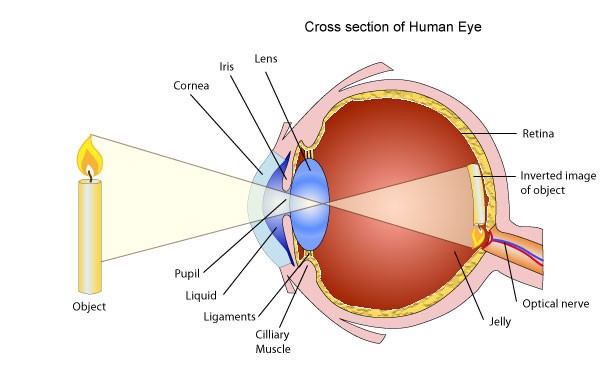
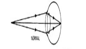
In general, light will enter through the iris, pass through the lens, and focus on the retina (note that the image focuses upsidedown!). A ray diagram for a "normal" eye is shown below.
With what we know about the eye and near and far sightedness, answer the following questions:
A. Sketch a ray diagram for near sightedness in the eye. It should include the lens of the eye, at least 2 light rays, the focal point, and the retina. Should anything about the structure of the eye be different from an eye without any vision problems? If so, what changes and how?
B. Repeat A. for far sightedness.
C. Parts A and B are your hypotheses for what happens in the eye when an individual has near or far sightedness. With these hypotheses, what do you propose for eye glasses in each case and why? Note that the choices here are convex or concave lenses. You should include ray diagrams in your argument.
D. If there are individuals in your pod that have eye glasses, they may volunteer their glasses for this part. It's beneficial to join with another 1-2 pods so you have at least 2 volunteered glasses. All grouped pods need to record the results in their own labbooks.
i) Ask the individual who volunteered their glasses if they are near or far sighted and whether they have a strong or weak prescription. Record this in your lab book(s).
ii) Using the 3 or 5 ray light source (you can try either or both!), conclude what kind of lens are in the eye glasses and what the focal length is. Does this match with your answers for A, B, and C? If not, redraw your ray diagrams and explain what's different.
iii) Repeat this proess (steps D. i-D. ii) for all volunteered glasses in your group. If you have more than one set of glasses for near and/or far sightedness, can you make any conclusions about the STRENGTH of the presrciption with regards to the focal length? If so, what and how does this relate to the ray diagrams of the eye you drew in parts A and B?
Appendix A - Error Calculation of Differentiable Functions
The error of differentiable functions can be approximated through differentiation.
Supposed we have performed an experiment from which we retrieved data represented by \(x \pm\delta x\). If we are interested in finding the \(f(x)\pm \delta f(x)\) , therefore, we are required to find \(\delta f(x)\). We begin by differentiating the function \(f(x)\) with respect to our variable \(x\). The resulting derivative is them multiplied by \(\delta x\).
\(\delta f(x) \approx \frac{df(x)}{dx} \delta x\)
As an example, supposed we have measured the angles of incident rays \(\theta \pm\delta \theta = 1.5 \pm 0.035~rad\) and we are interested in finding \(sin(\theta)\). Using the above formula, we are able to calculate corresponding error:
\(sin(\theta) \pm \delta sin(\theta) = sin(\theta) \pm \frac{dsin(\theta)}{d\theta}\delta \theta = sin(\theta) \pm cos(\theta)\delta \theta=sin(1.5) \pm cos(1.5)(0.035)\approx 0.997\pm0.002 ~rad\)
This Student Guide was written by Jason B. Harlow, Dept. of Physics, Univ. of Toronto, in the Fall of 2008. Part C of Activity 2 is by David M. Harrison, Dept. of Physics, Univ. of Toronto.
Revised: December 10, 2009 by Jason Harlow and Lilian Leung.
Revised February 3, 2011 by David M. Harrison
Revised July 23, 2011 by David M. Harrison and Brian Wilson