Electricity and Magnetism Module 5 Student Guide
Table of contents
 Activity 1
 Positive and negative test charges are placed inside a parallel plate capacitor as shown. These test charges interact only with the capacitor. Their presence does not alter the field of the capacitor, nor do they interact with each other.
-
An printable version of the diagram shown to the right is available in PDF Here. Print this page and staple it into your lab notebook. Use a black pen or pencil to draw the electric field vectors due to the capacitor inside the capacitor on that enlarged version.
-
Use a red pen or pencil (if available) to draw the forces acting on the two charges.
-
Pick a point of your choosing for the zero of potential energy. Label it “U = 0” on the diagram.
-
Is the potential energy of the positive point charge positive, negative, or zero? Explain.
-
In which direction (right, left, up, or down) does the potential energy of the positive charge decrease? Explain.
-
In which direction will the positive charge move if it is released from rest? Use the concept of energy to explain your answer.
-
Does your answer to part F agree with the force vector that you drew in part B?
-
Repeat steps D to G for the negative point charge.
 Activity 2 - Dielectric Permittivity of Air
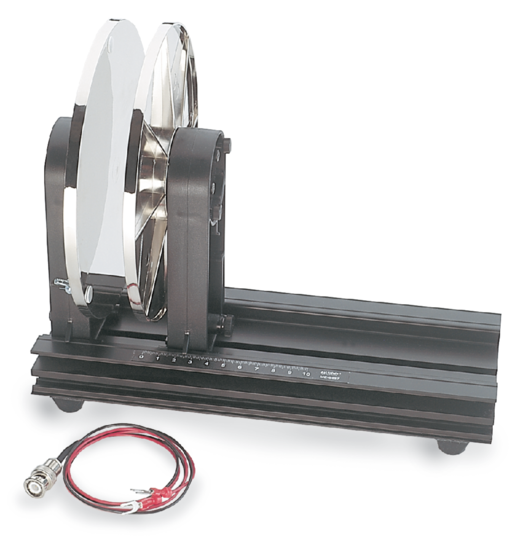
The purpose of this activity is to measure the dielectric permittivity of air, using a PASCO Basic Variable Capacitor (Model Number ES-9079). This is essentially two circular metal plates, mounted to be parallel, with their central axis horizontal, and a sliding scale to measure their separation.
-
What is the area of each circular metal plate, A, in m2?
-
Use a capacitance meter to measure the capacitance of the parallel plates, C, for a variety of separations, d. Note that when the metal clips are not attached to anything and are held far apart, the capacitance should read zero. You may need to adjust the zeroing knob on the capacitance meter to calibrate the measurement. Try to get a range of d from about 2 mm to 10 mm, and take measurements for at least 6 different values of d. You can use the calipers to make a precise measurement of plate separation. Convert d and C into SI units, and make a plot of A/d on the horizontal axis versus C on the vertical axis. The horizontal axis should have units of [m] and the vertical axis should have units of [F].
-
Fit a straight line through the data of your graph from part B. There are many ways of doing this. One may be to simply print the graph and use a ruler to sketch a straight line which seems to pass through or nearest most of the points. You should be able to estimate the slope and the uncertainty of the slope. The slope of your graph from part B should be equal to the dielectric permittivity of air in F/m. Should a straight line fit through the data necessarily pass through zero? Based on your fit, what is your measurement for ε for air for these data?
-
Compare your value to the vacuum permittivity of ε0= 8.85×10⁻¹² F/m . Is your measurement for permittivity of air consistent with the vacuum permittivity, or is your measurement significantly different from ε0 ?
Activity 3 - Dielectric Permittivity of Textbook Paper
To complete this activity, you will need to construct a parallel plate capacitor and use a capacitance meter to measure capacitance.
You can make a parallel plate capacitor out of two rectangular sheets of aluminum foil separated by pieces of paper. A textbook works well as the separator for the foil since you can slip the two foil sheets between any number of sheets of paper and weight the book down with something heavy and non-conducting like another massive textbook. You can then use your capacitance meter for the measurements.
Notes:
-
Insert the wires into the capacitance meter as “probes”. Note that when the metal clips are not attached to anything and are held far apart, the capacitance should read zero. You may need to adjust the zeroing knob on the capacitance meter to calibrate the measurement. When you measure the capacitance of your “parallel plates”, be sure that the aluminum sheets arranged carefully so they don’t touch each other and “short out”.
-
Paper acts differently than air when separating the plates of a parallel plate capacitor. For this experiment, you should have paper separating the plates over their entire area, for consistency.
-
What is the area of each square metal plate, A, in m2?
-
What is the thickness of one sheet of paper in your textbook, in m? You can use the calipers to make a precise measurement of a certain number of sheets, and then divide.
-
Use a capacitance meter to measure the capacitance of the parallel plates, C, for a variety of separations, d. Try to get a range of number of sheets of paper from about 5 to 50 pages, and take measurements for at least 6 different values of d. Compute the separation, d , in m, and convert C into SI units, and make a plot of A/d on the horizontal axis versus C on the vertical axis. The horizontal axis should have units of [m] and the vertical axis should have units of [F].
-
Fit a straight line through the data of your graph from part C. You should be able to estimate the slope and the uncertainty of the slope. The slope of your graph should be equal to the dielectric permittivity of paper in F/m. Based on your fit, what is your measurement for ε for textbook paper for these data?
-
What is the relative permittivity, κ, for the paper in your textbook, based on your data? How does your value compare to a google search?
Activity 4
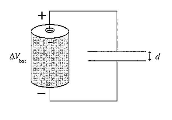 A parallel plate capacitor with plate separation d is connected to a battery that has potential difference \(\Delta V_{\rm bat}\), as shown. Without breaking any of the connections, insulating handles are use to increase the plate separation to 2d.
-
Does the potential difference ΔVC across the capacitor change as the separation increases? If so, by what factor? If not, why not?
-
Does the capacitance C change? If so, by what factor? If not, why not?
-
Does the capacitor charge Q change? If so, by what factor? If not, why not?
-
As the plates are being pulled apart, does current flow clockwise, counterclockwise, or not at all? Explain.
 Activity 5
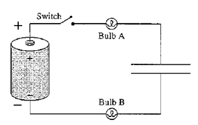
Light bulbs can be used to indicate current flow in a circuit. The brightness of a bulb increases with increasing current passing through it. The figure shows a battery, a switch, two light bulbs, and a capacitor that is initially uncharged.
-
Immediately after the switch is closed, are either or both bulbs glowing? Explain.
-
If both bulbs are glowing, which is brighter? Or are they equally bright? Explain.
-
For any bulb (A or B or both) that lights up immediately after the switch is closed, does its brightness increase with time, decrease with time, or remain unchanged? Explain.
Activity 6 - Capacitors, Batteries, and Light bulbs
Now let’s do an experiment using capacitors, batteries, and light bulbs to see what happens to the current flowing through a resistor (the bulb) when a capacitor is charged by a battery and then discharged. You are provided with a 6V 1W light bulbs, two capacitors (0.47 F and 1 F), and a 6 V battery. The capacitors are built using nanotechnology and are called supercapacitors; further information appears in the Appendix to this Guide.
-
Connect the light bulb in series with the 0.47 F capacitor, a switch, and the 6 V battery. Draw a circuit diagram of your setup. Describe qualitatively what happens when you close the switch.
-
Now, can you make the bulb light up again without the battery in the circuit? Mess around and see what happens. Describe your observations and draw a circuit diagram showing the setup when the bulb lights up without a battery.
-
Repeat parts A and B with a voltmeter across the capacitor. Draw a rough sketch of the voltage across the capacitor as a function of time for both cases.
-
Let's be more quantitative. In part A, we expect that the voltage across the capacitor will approach \(V_0\), the voltage of the battery, exponentially: \(\frac{V}{V_0}=1-e^{-t/RC}\), where R is the total resistance in the circuit in Ohms, and C is the capacitance in Farads. This can be re-written \(\ln\Big(1-\frac{V}{V_0}\Big)=-\frac{1}{RC}t\) . So, you expect a linear relationship if, on the vertical axis you plot \(\ln\Big(1-\frac{V}{V_0}\Big)\), and on the horizontal axis you plot t. The slope should be \(-\frac{1}{RC}\). If you trust the capacitance stamped on the capacitor, what is the resistance of the circuit? Repeat for the other capacitor, and compare your observations.
 Activity 7
The charge on the capacitor shown in the figure is zero when the switch closes at t = 0 s.
-
What will be the current in the circuit after the switch has been closed for a long time? Explain.
-
Immediately after the switch closes, before the capacitor has had time to charge, the potential difference across the capacitor is zero. What must be the potential difference across the resistor in order to satisfy Kirchoff’s Loop Law? Explain.
-
Based on your answer to part B, what is the current in the circuit immediately after the switch closes?
-
Sketch a graph of current versus time, starting from just before t = 0 s, and continuing until the switch has been closed a long time. There are no numerical values for the horizontal axis, so you will have to think about the shape of the graph.
Appendix – Supercapacitors
For a parallel plate capacitor with each plate having a surface area A, the plates separated by a distance d, and the space between the plates filled with a dielectric of constant \(\kappa\), the capacitance C is:
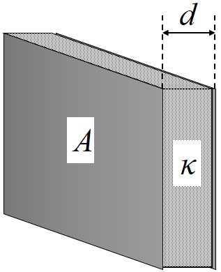 \(C = \kappa \frac{\epsilon_0 A}{d}\)
So there are three ways to increase the capacitance:
-
Use a dielectric with a higher constant.
-
Increase the surface area of the plates
-
Decrease the distance between the plates.
If the space between the plates is air and the plates are separated by 1 mm, then a 1 Farad capacitor must have a plate surface area of about 108 m2. For square plates this means the plates must be 10 km × 10 km.
Supercapacitors use nanotechnology to achieve extremely high effective surface areas. Often highly porous carbon is used, which can achieve effective areas of as much as 2000 m2 per gram. Although the basic idea was known as early as 1957, it is only since the mid-1990’s that advances in material science have led to reliable inexpensive supercapacitors.
Over time chemical redox reactions can occur on the electrodes which will degrade performance, and some manufacturers minimize this effect by making the two electrodes somewhat differently. Thus supercapacitors have their two terminals marked to indicate which is positive and which is negative. Some other more conventional capacitors, such as electrolytic types, also have a polarity. Using the correct polarity for supercapacitors extends their life somewhat but is not terribly important for our purposes. Electrolytic capacitors can explode if they are wired incorrectly.
This Guide was written in December 2007 by Kimberly Strong, Dept. of Physics, Univ. of Toronto. The Appendix was written by David M. Harrison, Dept. of Physics, Univ of Toronto in February 2008. The activities are based on Randall D. Knight, Student Workbook (Pearson, 2004) and Priscilla W. Laws, Workshop Physics Activity Guide, Module 4: Electricity and Magnetism (John Wiley & Sons, 2004).