PHY385 Module 5: Telescopes and Microscopes
Table of contents
 Activity 5.1 – Image Formation from Spherical Mirrors
EQUIPMENT NEEDED:
-Optics Bench, Light Source -Component Holder (3)
-50 mm F. L. Spherical Mirror -Viewing Screen
-Crossed Arrow Target.
Parallel rays can be brought to a focus by a reflective parabaloid of revolution. In this sense, a parabaloid reflector plays the same role as a lens in an optical system. It has a focal length and can be used to form an image of an object. For rays close to the optical axis, a parabaloid of revolution can be approximated by a spherical surface. In this activity, we will investigate a concave spherical mirror and apply the thin lens equation to its use in image formation.

Set up the equipment as shown in the figure above, with the concave side of the mirror facing the Light Source. The Viewing Screen should cover only half the hole in the Component Holder so that light from the filament reaches the mirror.
Adjust the position of the mirror until there is a well focused image of the crossed arrow target on the viewing screen. Make measurements of so and si for four or five values of so. Plot 1/so versus 1/ si and find the best fit line (linear fit). This should give a straight line with a slope of −1 and a y-intercept equal to 1/f. What is the measured value of f for this mirror? From this, what do you expect is the radius of curvature of this mirror?
Activity 5.2 – The Compound Microscope
EQUIPMENT NEEDED:
- Optics Bench - 75 mm Focal Length Convex Lens
- 150 mm Focal Length Convex Lens - Component Holders (3)
- Variable Aperture - Viewing Screen
A compound microscope uses two lenses to provide greater magnification of near objects than is possible using a single lens as a magnifier. The setup is shown in Figure 3.

Figure 3. The Compound Microscope
The lens, L1, functions as an objective. The object is placed just beyond, but very close to the focal point of L1, so a real, magnified, inverted image is formed. The eyepiece, L2, functions as a magnifying glass. It forms an enlarged virtual image of the real image, produced by L1.
The real image that is formed by L1 is magnified by an amount MTo = –si/so, as indicated by the Thin Lens Equation. That image is in turn magnified by the eyepiece by the factor of MTe = (250 mm)/f2. The combined magnifying power (see Hecht Section 5.7.5) is, therefore:
\(\begin{eqnarray*} {\rm MP} = \left(- \frac{s_i}{s_o} \right) \left( \frac{\rm 250 mm}{f_2} \right) \end{eqnarray*}\)
Set up the microscope as shown in Figure 3. Use the 75 mm focal length lens as the objective lens and the 150 mm focal length lens as the eyepiece. Begin with the objective lens approximately 150 mm away from the object (the Viewing Screen). Adjust the position of the eyepiece until you see a clearly focused image of the Viewing Screen scale.
- Is the image magnified? How does the magnification compare to using the 75 mm focal length lens alone, as a simple magnifier?
While looking through the eyepiece, slowly move the objective lens closer to the Viewing Screen. Adjust the position of the eyepiece as needed to retain the best possible focus.
- Why does the magnification increase as the objective lens is moved closer to the object?
- What focusing problems develop as the magnification increases?
Use the Variable Aperture to restrict the path of light to the central regions of the objective lens. Vary the size of the aperture and observe the effects on focusing.
- What effect does the aperture have on focusing?
- What effect does the aperture have on the brightness of the image?
- What advantage would there be in using a 75 mm focal length lens as the eyepiece?
Activity 5.3 – The Telescope
EQUIPMENT NEEDED:
-Optics Bench -75 mm Focal Length Convex Lens
-150 mm Focal Length Convex Lens -Component Holders (2)
Telescopes are used to obtain magnified images of distant objects. The image of a distant object when viewed through a single converging lens will be focused nearly at the focal point of the lens. This image will be real, inverted, and reduced in size. In fact, the greater the distance of the object (with respect to focal point f), the smaller the size of the image.
However, this reduced image is useful. By viewing this image through a second converging lens—used as a magnifier—an enlarged image can be seen.

Figure 1. The Telescope
Figure 1 shows the setup for a simple telescope. The objective lens, L1, creates a real, inverted image. (You can barely see this image in the diagram. It's very small, just inside the focal point of lens L2.) If the object is sufficiently far away, this image will be located approximately at f1, the focal point of L1. The eyepiece, L2, then acts as a magnifier, creating a magnified, virtual image which can be viewed by the observer. For maximum magnification, L2 is positioned so the virtual image is just slightly closer than its focal point, f2. Therefore, the distance between the objective lens and the eyepiece of a telescope, when viewing distant objects, is approximately f1 + f2.

Figure 2. Telescope Magnification
The angular magnification for a telescope can be approximated by assuming the lenses are exactly f1 + f2 apart, as shown in Figure 2. The height of the object as seen with the naked eye is proportional to the angle θ1 in the lower diagram. If the distance from the object to the telescope is large, much larger than is shown in the diagram, then θ1 is the same in both diagrams, to a good approximation. The ray shown in the upper diagram passes through the focal point of the objective lens, comes out parallel to the optical axis of the telescope, and is therefore refracted by the eyepiece through the focal point of the eyepiece. The angle θ2 is therefore proportional to hi, the height of the image seen by the observer.
Theory
- Using Figure 2, calculate tan θ1 and tan θ2 as a function of the height of the image, hi, and the focal lengths of the two lenses, f1 and f2.
Assume that θ1 and θ2 are very small, and therefore equal to tan θ1 and tan θ2, respectively.
- Calculate the angular magnification of the telescope, MP = θ2/θ1.
Experiment
Set up a telescope using the 75 mm and 150 mm focal length lenses; the distance between the lenses should be approximately 225 mm. Using the 75 mm lens as the eyepiece, look at some reasonably distant object. Adjust the distance between the lenses as needed to bring the object into sharp focus.
To measure the magnification, look with one eye through the telescope, and with the other eye look directly at the object. Compare the size of the two images. (If a repeating object is used, such as venetian blinds or bricks in a wall, you should be able to estimate the magnifying power fairly accurately: if 3.5 bricks viewed without the telescope overlap with one brick viewed with the telescope, then MP = 3.5×.)
- What do you measure as the magnification of the telescope when using the 75 mm lens as the eyepiece? Compare with the prediction of Part B.
- What is the magnification of the telescope when using the 150 mm lens as the eyepiece and the 75 mm lens as the objective lens?Compare with the prediction of Part B.
Activity 5.4 – Building a compound microscopes with a smartphone or a digital camera
EQUIPMENT NEEDED:
-Optics Bench, Light Source -Component Holder (2)
-Ray Optics Mirror -Cylindrical Lens
-Lab Jack -Specimen Stage (see Fig. 1)
-Camera Stage with two built-in lenses (see Fig. 1) -Set of Samples
-Transparent film with different grids and patterns -Caliper, Ruler
-Smartphone (provided by a student) or a digital photo camera (provided by the lab).
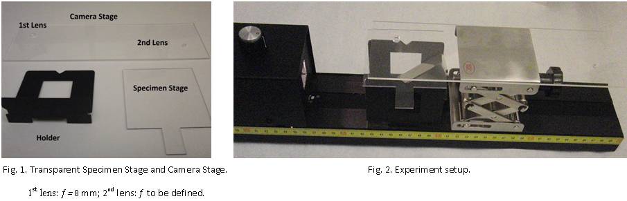
Mount equipment on the Optics Bench as shown in Fig. 2.
- Put two holders parallel to each other and aligned with the Optics Bench to use them as supporters for the Specimen Stage.
- Attach the Ray Optics Mirror onto one of the holder to illuminate the sample on the Specimen Stage.
- Turn on the light and adjust the position of the flat mirror so that a bright light strip appears on the specimen stage.
- Place the Lab Jack on the Optics Bench as shown.
- Put a sample you will study on the specimen stage just above the light strip reflected from the mirror.
- Place the Camera Stage on top of the Lab Jack and align the larger lens with the sample under it.
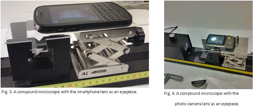
- Turn on the camera in your smartphone and align the camera lens with the objective lens in the Camera Stage by looking from the camera screen. Your setup will look like in the Fig.3. You may fix the well aligned position of the two lenses by attaching the smartphone and the Camera Stage be a tape.
- If you do not have a smartphone, a compact photo camera can be provided. Then your setup will look like in Fig. 4.
- Adjust the height of the camera stage by turning the knob on the lab jack. When the image is focused, zoom in to obtain the higher magnified picture as the final image.
Measurement of the microscope magnification. (This Activity must be accomplished in not more than one hour).
- With the caliper, measure and record the diameter of three different wires (Brown, Red, and Yellow)
- Use your setup with the 1st lens with f1 = 8 mm (the largest one) to take pictures of each wire, and measure the diameter of the wire's image on the screen with a ruler.
- Apply the formula M1 = di / do to calculate the magnification of the 1st lens. Write down the average value of M1 into the notebook and save the images of the three wires in the computer.
- To estimate the angular magnification of the eyepiece, use the formula for the magnification of the compound microscope as M1 =(L1/f1 ) me , where L1 is the distance between the two lenses; and me is the angular magnification of the eyepiece. Using the ruler define the approximate distance L1 and calculate me.
-
Turn the Camera Stage 180° about a vertical axis to set the smaller built-in lens as an objective lens. Restore the smartphone or a photo camera on the Camera Stage and align the system.
-
Repeat the above described measurements of the diameter of three wires with the second lens and find the magnification of the microscope. Save the images of the three wires in the computer.
-
Measure the distance L2 and assuming the angular magnification of the eyepiece a constant, estimate the focal length of the 2nd lens (the smaller lens). Write the result in the notebook and give a brief list of the main sources of uncertainties of this value.
-
Enjoy taking images and measuring the size of a human hair and of the table salt crystal. Give an approximate value for the hair thickness and the salt crystal size and shape. If time permits, take images of the green leaf cells, white sand crystals, black pepper powder that can be provided by the lab and whatever you wish to satisfy your curiosity.
Save the best images of the hair and the table salt crystal.
This activity was created by Natalia Krasnopolskaia in October 2014.
 Activity 5.5 – Problem Solving
- If a photograph of a moving merry-go-round is perfectly exposed but blurred, at \(\frac{1}{30}\)s and and f/11 what must the diaphragm setting be if the shutter speed is raised to \(\frac{1}{120}\)s in order to "stop" the motion ?
- Problem 5.53 from Optics by Hecht, ed. 5
This activity was added by Damya Souami in October 2014. The questions are from Optics by Hecht, ed.5