PHY385 Module 7: Diffraction
Table of contents
 Activity 7.1 – The Diffraction Grating
Equipment Needed:
- Optics Bench
- Light Source
- Ray Table Base
- Component Holder
- Diffraction Scale
- Diffraction Plate
- Diffraction Grating
- Slit Mask
- Colour Filter (any colour).Perform in a well-lighted room.

Figure 1. Equipment Set-up for Activities 7.1 and 7.2
Diffraction gratings are used to make very accurate measurements of the wavelength of light. In theory, they function much the same as two slit apertures (recall Activity 4.1 from the 4th practicals session). However, a diffraction grating has many slits, rather than two, and the slits are very closely spaced. By using closely spaced slits, the light is diffracted to large angles, and measurements can be made more accurately. In spreading out the available light to large angles, however, brightness is lost. By using many slits, many sources of light are provided, and brightness is preserved.
In this experiment you will use a diffraction grating to determine the range of wavelengths for each of the colors in the visible spectrum.
- Arrange the equipment as shown in Figure 1, except add the blue part of the BLUE/GREEN FILTER in front of the light source. When looking through the Diffraction Plate window, the filament of the Light Source must be directly visible through the slot in the Diffraction Plate. Look through each of the double slit patterns (Patterns D, E, and F) of the Diffraction Plate at the filament of the Light Source. Recall from session 5:
Pattern D has 2 slits spaced a = 0.125 mm apart, each of which are b = 0.04 mm wide
Pattern E has 2 slits spaced a = 0.250 mm apart, each of which are b = 0.04 mm wide
Pattern F has 2 slits spaced a = 0.250 mm apart, each of which are b = 0.08 mm wide
Pattern G has 10 slits, spaced at every a = 0.250 mm, each of which are b = 0.06 mm wide
Qualitatively, compare the spacing of the interference maxima for double slits D, E and F. Which determines the fringe spacing, a or b?
- Look through the 10-slit pattern (Pattern G) at the filament.Compare it to Pattern F. What effect does the larger number of slits have on the diffraction pattern?In particular, count the number of fringes in the brightest bunch at the center of the pattern.
Remove the Blue/Green Filter, the Diffraction Plate and the Slit Mask. Replace the Diffraction Plate with the Diffraction Grating. Note that the Diffraction Grating has about 20,000 slits, spaced at every a = 0.0017 mm, each of which are about b = 0.001 mm wide. Look through the grating and observe the first order spectrum.
NOTE: When looking through the Diffraction Grating avert your eye from looking straight at the filament. Instead, look at a position on the Diffraction Scale about 4 to 5 cm to the right or left of the slit in the scale.

Figure 2. Measurements with the diffraction grating.
The grating equation is: mλ = asinθ, where m is the order number. We are working in the m = 1 order.
- For each colour range, identify the minimum and maximum value of the apparent positions of the colors on the Diffraction Scale, X1 and X2.Knowing that a = 0.00167 mm, and measuring the distance between the diffraction grating and the diffraction scale L, you should be able to solve for the minimum and maximum values of λ, and fill these into a table in your notebook similar to Table 1. λ1 and λ2 are the minimum and maximum wavelengths, respectively, defining the range of wavelengths corresponding to each particular color of light.These are estimates only; different teams may have slightly different definitions of these ranges.
|
|
Data, L = |
Calculations |
||
|
Color |
X1 |
X2 |
λ1 |
λ2 |
|
Violet |
|
|
|
|
|
Blue |
|
|
|
|
|
Green |
|
|
|
|
|
Yellow |
|
|
|
|
|
Orange |
|
|
|
|
|
Red |
|
|
|
|
Table 1.
Activity 7.2 – Single Slit Diffraction (as observed with your eye)
Equipment Needed:
- Optics Bench
- Light Source
- Ray Table Base
- Diffraction Scale
- Component Holder
- Diffraction Plate
- Slit Mask
- Colour Filters (Red, Green, Blue/Green)Perform in a well-lighted room.
If you look closely at a two slit interference pattern, you will notice that the intensity of the fringes varies. This variation in intensity forms an interference pattern of its own that is independent of the number of slits or the separation between the slits. In fact, two slits are not required to see this pattern; it can be seen most clearly when light passes through a single, narrow slit.
In this experiment you will compare the single slit diffraction pattern with the double slit pattern, and then use the single slit pattern to measure the wavelengths of red, green, and blue light.
Setup the equipment as shown in Figure 1. Look through each of the three single slit apertures in the Diffraction Plate (Patterns A, B, and C). Examine the diffraction patterns with and without color filters over the aperture of the Light Source.
Pattern A has 1 slit of width b = 0.04 mm
Pattern B has 1 slit of width b = 0.08 mm
Pattern C has 1 slit of width b = 0.16 mm
- Are fringes observed?If so, how does the spacing between fringes vary with the width of the slit?

Figure 3. Geometry of Single Slit Diffraction
The single slit pattern can be explained using Huygen’s theory. When a plane wave front strikes the slit, each point on the slit acts as a point source of light. Figure 3 shows a point P, far from the slit, where the distance AP = BP + λ. Since light from point A travels one wavelength farther than light from point B, the light from these two points is in phase at point P. But light reaching point P from the points in between A and B will vary in phase through a full 360°. For any point from which light reaches point P at a particular phase, there will be a point from which light arrives in the exact opposite phase. Because of this, there is complete cancellation at point P, and a minimum (dark fringe) will be seen at that point.
In the Figure, point P is at an angle θ from the center of the slit. We make the assumption that point P is far enough away such that AP and BP are very nearly parallel (this is true in reality, if not in the diagram). As shown in the diagram, angle ABC = θ , also. Therefore W sin θ = λ; where W is the width of the slit (AB). A similar argument can be used to show that a minima will be found at any angle such that W sin θ = nλ , where n is any integer. n = 1 will be the first dark fringe next to the central maximum.
Review the two slit interference experiment. Notice the similarity between the equations for single and double slit patterns. To measure the wavelength of light, use the same techniques you used in the two slit experiment (θ = arctan X/L). When measuring the distance to the minima (X) for each color, place the Color Filter on the front of the Light Source. Fill in a table in your notebook similar to the one below, and from your single-slit data, determine the average wavelength of Red, Green, and Blue Light.
|
Data |
Calculations |
|||||
|
Color |
n |
W |
X |
L |
arctan (X/L) |
nλ = W sin[ arctan (X/L) ] |
|
Red |
|
|
|
|
|
|
|
Green |
|
|
|
|
|
|
|
Blue |
|
|
|
|
|
|
Activity 7.3 – Patterns projected on the screens by a laser
Design an experiment to compare one single-slit pattern to one double-slit pattern as projected onto a viewing screen using one of the three lasers in your box.
- Which laser did you choose, and why?
- Exactly which double-slit pattern and which single-slit pattern did you compare, and what were their properties?
- Use the double-slit pattern to estimate the wavelength of the laser.
- Using the wavelength from part C, make a prediction for the slit-width which produced the single-slit diffraction pattern you observed.Does this match your data for the single-slit width as given in the handout?
 Activity 7.4 – Poblem solving
Problems 10.7, 10.13, and 10.15 from the book (Optics by Hecht, ed. 5)
Activity 7.5 – CDs and DVDs as Diffraction Gratings
During the lecture, we have observed diffraction of light waves through a CD and a DVD. This practical is meant for you to deepen the understanding of this phenomenon.
Equipment Needed:
- Optics Bench
- Lasers
- DVDs and CDs
- Diffraction Scale
- Screen
- Mount
 (Google search image)
The digital information stored on the disc where we observe alternating pits and lands as shown on the figure above.
When looking at the back side of a digital disc we observe reflecting diffraction gratings, where each wavelength can be seen at a particular angle (that is because of constructive interference for that wavelength in taht direction).
here we are interested in the transmission diffraction gratings. You are given a CD and a DVD, the label surface has been peeled off the surface of the CD. As for the DVD the polycarbonarte layer has been separatated using a knife, you will only be using transparent piece that transmits light.
The difference is data storage capacity fom one disc to another is a result of the spacing between the pits. For instance for a DVD it is about \(0.75 \mu\text{m}\). Set up the equipment as shown on the figure below
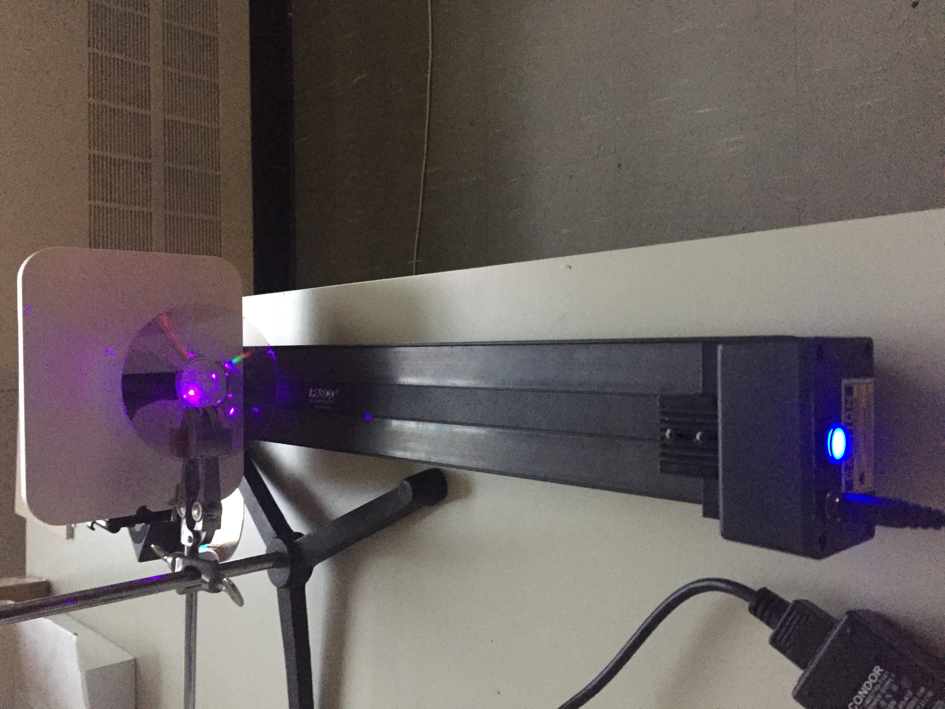
- Consider the spacing between the pits for a DVD to be instance \(0.75 \mu\text{m}\). Use the DVD as a diffraction grating for transmitted light with the blue then the green laser and measure their respective wavelength
- Now, using this same set up, measure the spacing between the pits for the CD by using as a diffraction grating for transmitted light with the blue then the green laser. For a CD, the distance between the pits is about \(1.6 \mu\text{m}\), how does this compare to your results?
Developed by Damya Souami in November 2016